Archives for category: Videogames

In my previous post I tore apart a Famiclone aka NOAC (Nes On A Chip) with the grand name of Twin Lightblaster Joypad. Today I’ve gone further, by miniaturising and modding the circuit further to fit inside of a NES or Famicom controller.

I had to do three things:

– Get it running of off external power
– Cut the second D-Pad (bottom middle of the board)
– Wire connections for the controls

Running from external power was easy. I hooked up my variable bench power supply I’d recently built with an LM317 regulator (see this Afrotechmods video on YouTube) and set it to just under 6v. Switched it on. Bingo!

Next I followed the AV back up the board to where I could get a signal (a row of inductors), cut the second d-pad out, rewired and tested. First time I got a picture (see the multi ROM in the below picture). And it shrank the board by almost a third.

Next up: Buttons!

The thinking went: As the AV signal went past the D-pad, I could hook up on the same set of traces. It turned out even better, as the traces ran to the same set of inductors. I soldered these up using some cabling out of and old Ethernet Cat 5 cable, then grounded each, noting the colour and direction.

The Famicom, unlike the NES, only has Start and Select on the first controller (marked I), however this clone has those buttons on the second controller. Could I then hook up those buttons on the nice solder pads left when I desoldered the second port? Dabbing around with a ground wire, I shorted one of the pads and the whole thing died.

One thing I had noticed on this board in the tear down was the reverse polarity protection (a parallel diode and a fuse). Luckily it was only the fuse killed – jumping across it brought the thing back to life. A new one has been ordered from eBay.

To finish up, I soldered up to the button pads on the board directly. Then gave everything some thick glue gun glue and some insulating tape to keep everything secure and less likely to short.

And here’s where I left it:

Back of the board with AV and controls wired

And the front of the board with Ethernet wires soldered on. The cut second D-pad on the right.

Video from [Legion2000] on YouTube

Another purchase from the car boot was this £1 curio. It’s a NOAC (NES On A Chip) Famiclone. Two controllers, one that hooks up to the TV (containing 4 x AAA) and a second that connects to the first. They’re intended to look like N64 controllers, but the hardware inside is a NES clone with 21 games (see this great post on NOACs by Ben Heckendorn).

The 21 titles are original NES games reskinned with new, often bizarre, graphics. Particularly odd is the Super Mario Bros clone called Panda. Very bleak. Very existential.

On the bottom is an edge connector for Famicom carts. Although the hardware is the same the connection across the NES and Famicom are different (there are more, albeit unconnected, pins on a NES cart). It also has a Zapper built in and a little trigger where you’d find the Z button on an N64 controller. Duck Hunt has been reskinned as an alien shooter and Hogan’s Alley has animals with guns.

Here it is cracked opens. Those three black blobs are where the ROMs and NOAC are. The lead out the bottom is composite video and L & R audio. Although they’re wired together as the NES is mono. Also at the bottom is the D-sub connector for the second controller. A Master System or Mega Drive controller fits, but I haven’t tested. I wouldn’t be suprised if they used the same control scheme as there’s no shift registers used in the NES in the system.

Composite leads.

Composite coming off of the board. Not the neatest soldering job I’ve seen. These connections, like a lot of the board, was covered in a thick glue.

The D-sub player 2 port and the trigger button. At the top of the picture you can see two LEDs and the sensor for the “Lightblaster”. The two LEDs seemingly have no function, but come on when you shoot. Totally pointless because you’re looking down the barrel anyway. I only noticed they came on when I saw their reflection in the screen.

The intention is to do something cool with this at some point. Possibly putting the whole lot inside an original NES controller. So, I decided to desolder the light gun parts: The sensor, two LEDs and the trigger. Here’s the back.

And the front. The two wires you can see at the top are the power inputs, nicely colour coded (red +, black -). These were wired to two springs which connected to the battery cartridge. The cartridge fits in to the expansion slot, like a rumple pack, housing the AAAs and springs back out again. Nice design feature.

The buttons short across those pads using rubber domes with carbon sections in, grounding the buttons. There appears to be some tidy places to solder in to as I know there are in a NES pad, so could be an easy weekend hack to finish up.

All I now need are:

In my last post I explained how I managed to open up a SEGA cart. The Master System uses a 28 pin mask ROM, which can be replaced by a 27c series EPROM easily. I’ve seen people building EPROM carts using these chips for Mega Drive.

So, when on opening the Mega Games 1 cart I had I found a 42-pin Mask ROM I was a little confused.

Here’s the PCB.

My thinking is this: The Master System is a 8-bit machine, so the cart has 8 data bits, 16 address bits, V+, GND and some other things, like chip enable.

The Mega Drive is a 16-bit machine however, so it would have 16 data bits and 16 address bits. Doing a bit research that appears to be accurate.

Here’s a schematic of a cart (using two AT49F040 Flash chips) on Ralphnet.net

One thing I’ve always wanted to build is a SEGA or Atari flash cart. My GF has ordered me an EPROM programmer and I so I grabbed some Winabond w27c512 EEPROMs.

While waiting for those to arrive from Hong Kong, I needed to source some donor carts. So went car booting.

I picked up Tennis Ace and Sonic the Hedgehog 2 for the Master System and Mega Games 1 for the Mega Drive for £4.

There’s a brilliant how to on the Little-Scale blog for a write-once 32KB cart, but there’s little info on how to open the security screws. And they’re genuine bastards.

The screws are round topped with small notches on opposing sides.

I have a nice set of security bits, but nothing right. The closest was a flat head bit with slot cut out in the centre. Could those line up and turn the screw? No. The slot was too small.

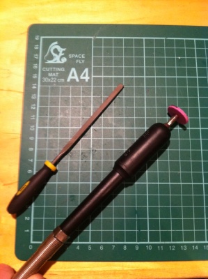
The solution was to Dremel out the slot (lots of sparks) and tidy with a hobby file.

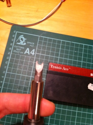
After a test fit or two, the final bit.

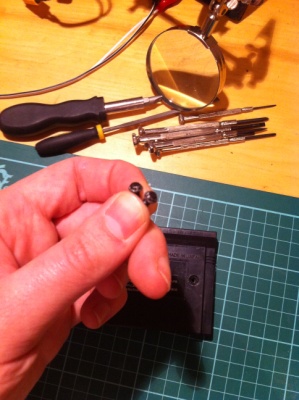
It was not a perfect fit. It chewed the plastic around the screw holes and the screws themselves (as you can see in the photo below). You could do this with any flat head bit of a suitable width.

Mangled. But these aren’t going back in anyway. I had some other, more maintenance-friendly, Phillips headed screws from some dead bit of electronics.

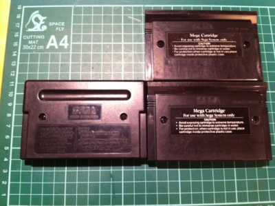
Open and shut case. Here’s the carts with new screws. Simple.

I’d always wanted my very own arcade cab, but never had the space. So, when I had a loose weekend, an old Android device and some MDF I had to make this miniature cab-shaped phone stand.

Video at the bottom of this post.

The construction was pretty simple: All MDF was cut from a template with a jigsaw, then glued and clamped, sanded and finished with black spray paint.

For the paint I used graffiti paint that you get from art shops. It’s much higher quality than Odds ‘n’ Ends or other automotive paint you might get, so highly recommend sourcing some.

The artwork was printed from vector to semi-gloss photo paper using an inkjet. This was glued on or stuck with double sided tape. I used Pritt Stick, which as you can guess, wasn’t very strong, so peeled. If I were to redo this now I’d use sticker sheet.

The device is a Orange San Francisco (aka ZTE Blade), which is a lovely cheap device with an OLED screen (later models had less fantastic screens). It’s fully rooted and running Cyanogen Mod 7.

The MAME port is called MAME4Droid (Marketplace) and is, again, excellent. It’s based on an older MAME version, so doesn’t support all ROMs. But you’ll only be running ROMs for those machines you own, right? RIGHT?!

The Wimote hooks up over Bluetooth using Wiimote Controller (Marketplace). This is a bit of a hack as it sends buttons by appearing as a software keyboard to apps. You may also need to manually find and input the BT address of the Wiimotes by using another app (see help in Wiimote Controller app).

You can configure the buttons in MAME4Droid. All except coins, which you’ll need to do manually with an on screen button.

And here it is in action: